Unmanned Ground Vehicle
During the 2020-2021 UAV Forge competition season, I was tasked with redesigning the mechanical portion of our unmanned ground vehicle (UGV). Previously, the team used an off-the-shelf remote control car to accomplish the ground vehicle tasks. However, this left the weight, top speed, and power draw of the UGV relatively fixed.
The RC car was not designed to withstand the impact of repeated testing (descent and landing from 100+ foot altitude), the amount of space available for electronics was not sufficient, and replacement parts were not readily available for repairs. These three attributes were the main focuses for redesign. We were able to successfully design and manufacture a UGV that was 40% lighter and satisfied all major requirements.
Pugh Analysis
To begin the design process for the UGV redesign, a Pugh Analysis was conducted to narrow down design options. The team utilized a Pugh Analysis to determine a baseline for which designs to consider. Justification for specific values in the analysis can be found under the “Concept Selection” section of the UGV Design Documentation document.
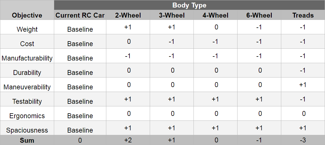
Research was conducted on common UGV designs in addition to other designs successfully employed in the AUVSI-SUAS competition. The two-wheel design was ultimately chosen as a starting point for our final design.
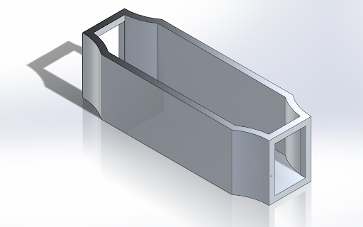
Chassis Design
Upon selection of the two-wheel drive system, we designed a chassis to fit three primary requirements. These requirements were derived from other subteams and the competition rules:
- The chassis must be large enough to fit all of the required electrical components.
- The chassis must be light so that the UGV does not exceed the 4 lb competition-imposed weight limit.
- The chassis must have a clear plan for manufacturing.
More detailed requirements and objectives for the chassis design can be found in the Chassis Design Documentation document.
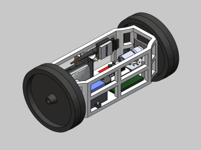
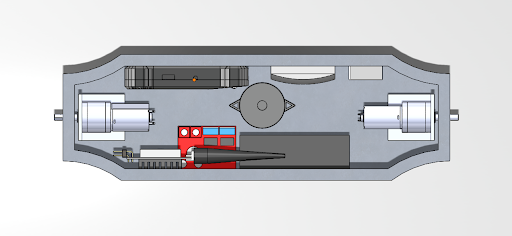
CAD models of electronic components were taken from manufacturers’ websites or created in-house. Electronics were placed in the chassis assembly to ensure sufficient space was available when assembled.
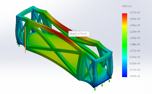
Static load simulations were utilized to determine how the chassis would react under worst case-scenario conditions during impact with the ground. Forces were estimated based on the momentum-impulse equation and input into a Solidworks Static Load Simulation.
Weight Reduction Cutouts
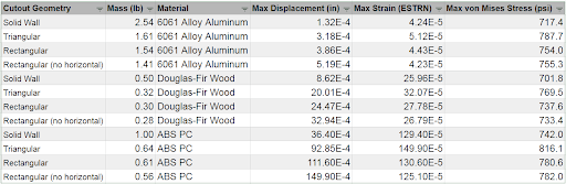
Various cutout geometries were tested under identical loading conditions. Beam thicknesses and configurations were varied, with maximum stress, strain, and displacement documented for comparison.


Tabulated simulation results are displayed in the figure below. To come in under the four pound weight limit, we calculated that our chassis could weigh no more than 0.85 pounds. Rectangular cutouts were chosen because they provide the lowest stress distribution for all configurations under the 0.85 pound limit.
The selected configuration was manufactured and presented at UAV Forge’s Winter Internal Design Review.
Material Selection
The primary criteria for material selection for the chassis were manufacturability, access to tools, and cost. Wood, plastic, and aluminum were the three materials that were considered. Based on the cutout geometry configurations, aluminum would have been an impractical choice due to weight restrictions on the UGV. With wood, we were concerned about manufacturing the precise geometry of the cutouts with hand tools, and access to CNC machinery was not available to the team. UAV Forge has convenient access to a 3D printer, and ABS plastic designs were well within the weight budget.

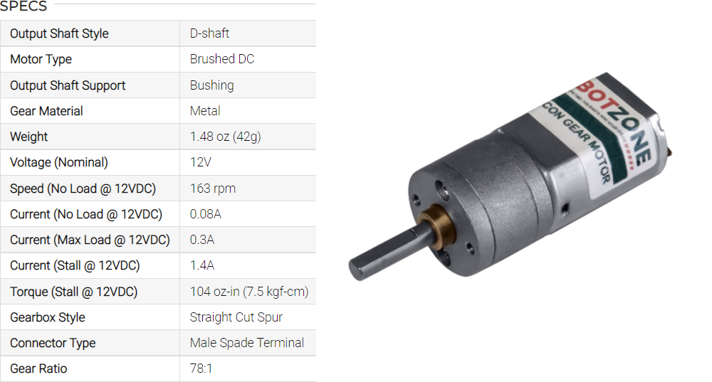
Motor Selection
Two forces are considered to estimate the torque required for the ground vehicle motors: acceleration forces and frictional forces. To move, the ground vehicle must overcome the frictional force between the wheels and the ground as well as the force required to accelerate the vehicle from rest. In general, frictional forces contribute a greater proportion of total force, so variables such as time to accelerate and maximum velocity are less important to accurately estimate.
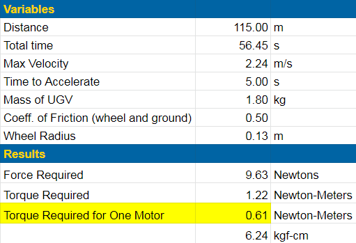
After conducting research, the 163 RPM Mini Econ motor was selected. The motor fits the torque requirements and provides adequate RPM for the ground vehicle to move to its desired location.