Autonomous Fixed-Wing Aircraft
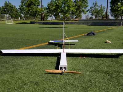
In 2021, I was part of a senior design project team whose objective was to design, manufacture, and test an autonomous fixed-wing aircraft. The goal was to design a modular fixed-wing test bed that flies for 10 minutes carrying 1 pound of payload. UAV Forge would use the plane as a proof of concept for a fixed-wing design and for developmental testing. My roles on the team were structural design of the wing mount, CADing the plane assembly, and fabrication.
Wing Mount Design
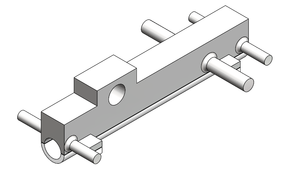
The aircraft wings were manufactured separately from the fuselage to make the aircraft modular and transportable. An attachment mechanism needed to be designed that allowed for quick assembly while being rigid enough for flight. A clamping mount was chosen so that the wing’s position along the fuselage could be changed.
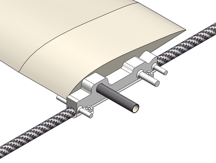
Since there were strict schedule restrictions and the geometry of the wing-attachment mechanism was fairly complex, we decided to 3D print the part. We chose ABS plastic as the material due to its rigidity and availability.
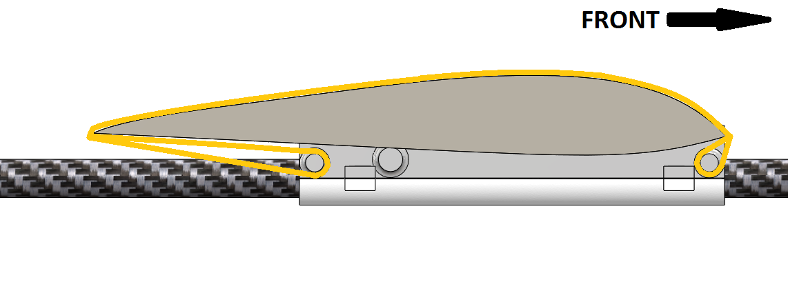
Tensioning was utilized to fix the wing to the wing-attachment mechanism. In the figure above, the orange color represents rubber bands that tension the wing to the fuselage. This strategy allows for convenient assembly and will act as a point of failure in a crash so that the wings do not absorb all of the force. Moment estimations were conducted on the circular struts that protrude from the part to ensure they would not break from tension forces.
Topology Optimization Study
One of the primary goals of the structural design was to reduce the aircraft’s weight. After obtaining an estimate of the forces the wing-attachment mechanism would endure in a crash and in flight, a topology optimization study was conducted to analyze areas where we can cut material without sacrificing structural integrity.
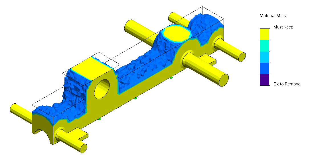
We superimposed the optimization results onto our initial model of the Solidworks part and manually cut away unnecessary structure. Ultimately, we were able to reduce the weight of this part by 15% while maintaining a factor of safety of two.

Static Load Simulations
After the topology optimization simulations were conducted, static load simulations were run on the part to ensure it would withstand a crash. Back of the napkin calculations were done to produce a max force value that the aircraft would experience in a crash. The momentum-impulse equation was used to estimate the force, which we applied to a static load simulation in two different scenarios. One where the force is concentrated on the circular struts, and one where the force is concentrated where our carbon fiber wing spars would intersect with the part.
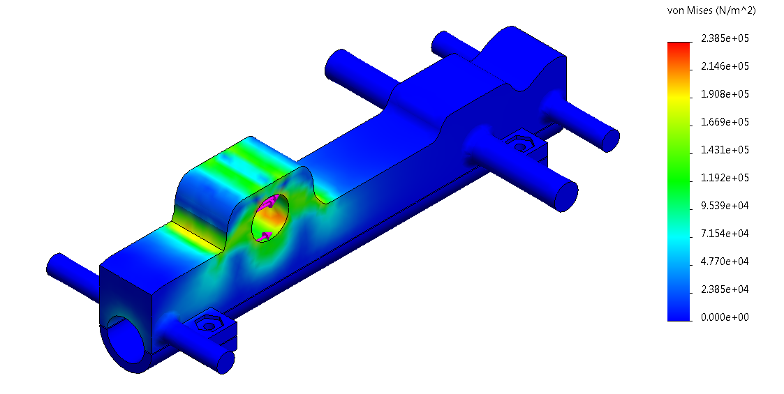
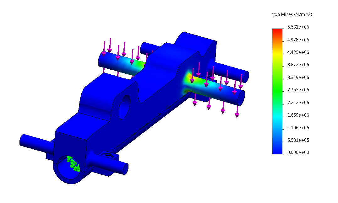
We determined that in either case, the maximum stress experienced by the part would be significantly less than the 20 MPa maximum stress threshold of 40% infill ABS [1]. We 3D-printed the design and used it on the final iteration of the aircraft.
References
[1] G. Johnson and J. French, “Evaluation of Infill Effect on Mechanical Properties of Consumer 3D Printing Materials,” Advances in Technology Innovation, vol. 3, no. 4, pp. 179-84, July 2018.